E-MU Proteus Battery Replacement
The 1991 Proteus/3 World would not keep changes in memory. This reduces the number of voices by 1/3. The case was opened and the battery was tested at 0.2 VDC. The board needs 3 VDC to support the RAM chip.
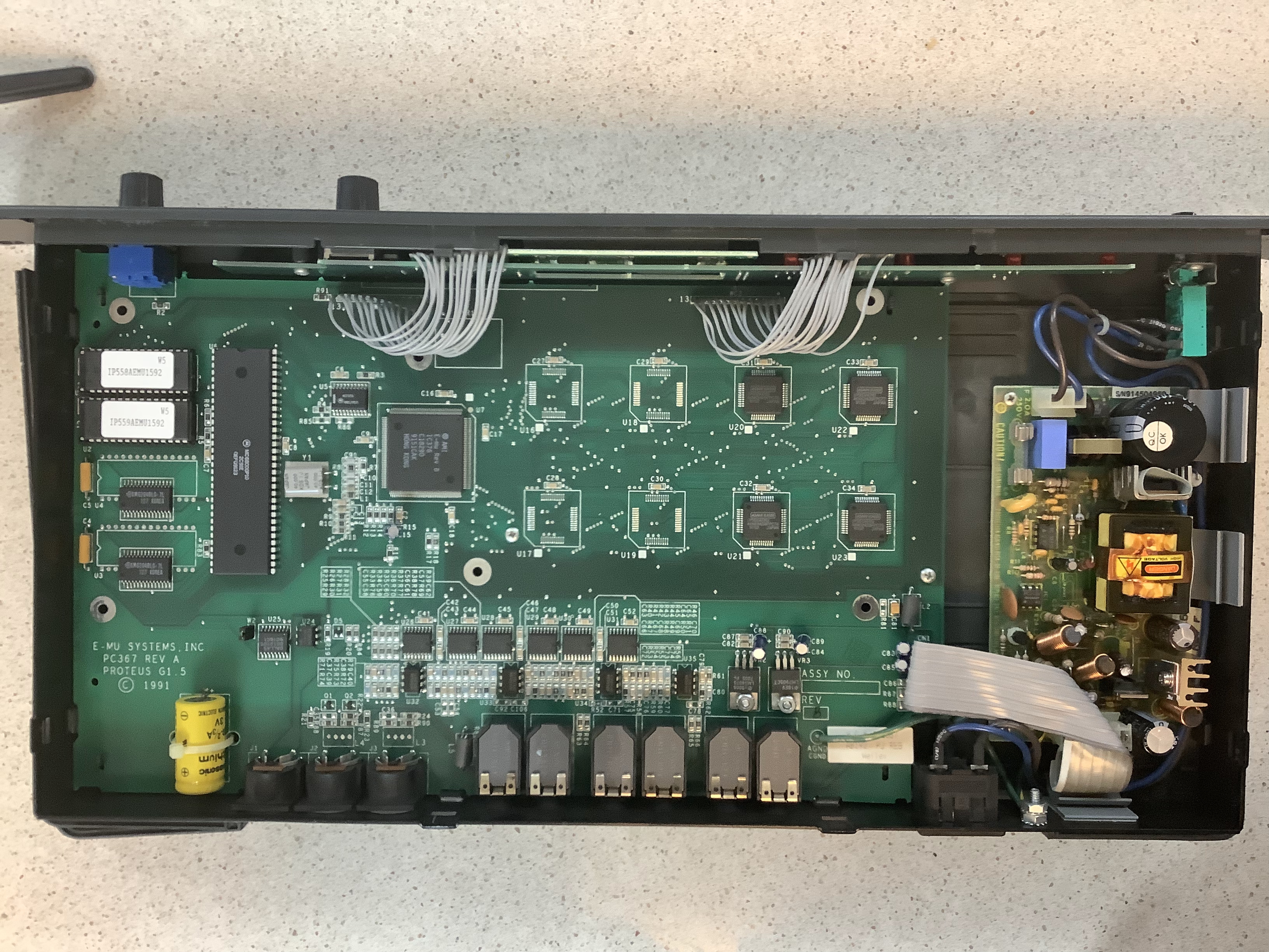
This picture shows the top off of the case off. There are internal tang tongues along the sides and back. A regular screwdriver is used to bend the tongues over to allow release of the half case.
Order the battery BR-2/3AE5SP. The battery has two pins attached for a micro solder PCB board. The BR-2/3A 3V lithium battery comes without or with pins and there are several pin configurations available. The E5SP is the one needed for these older Proteus boards. Note the tie-wrap. It holds the battery in place for soldering and provides support. Note the tang tongues that hold the case to the frame. Two on each side and two in the back for each half-case.
The board is held in place with two screws. The power supply is held in place with four screws. Remove these six screws before you remove the bottom half-case. The power board will float when the entire case is removed. Use care to protect the flat Molex cable.
:
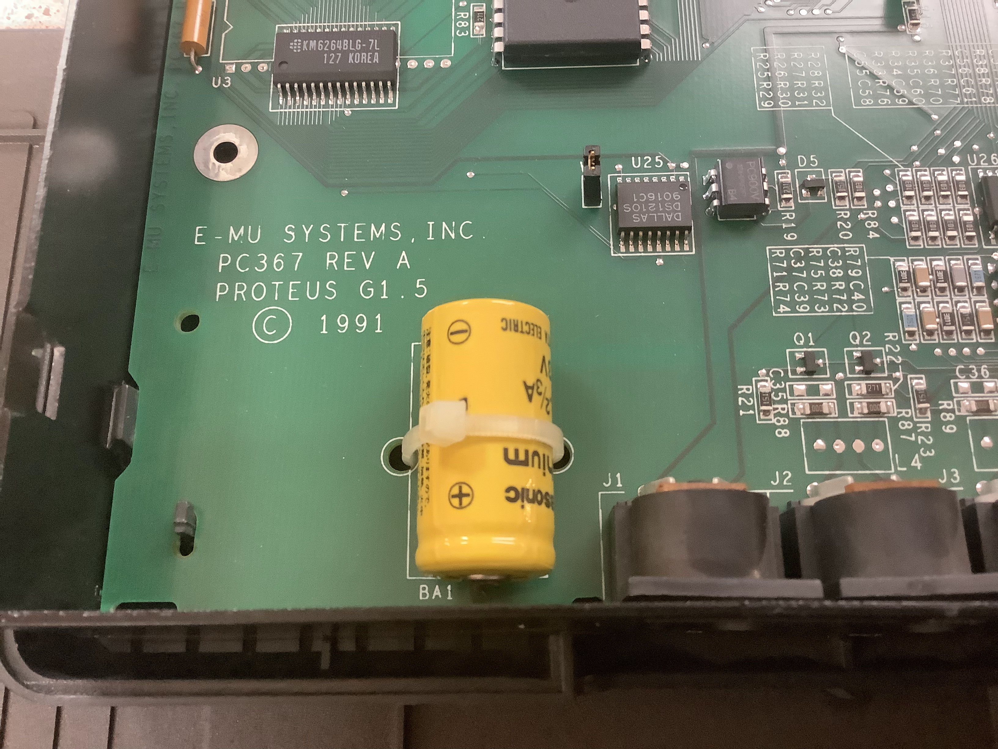
Close up of the old battery.
:
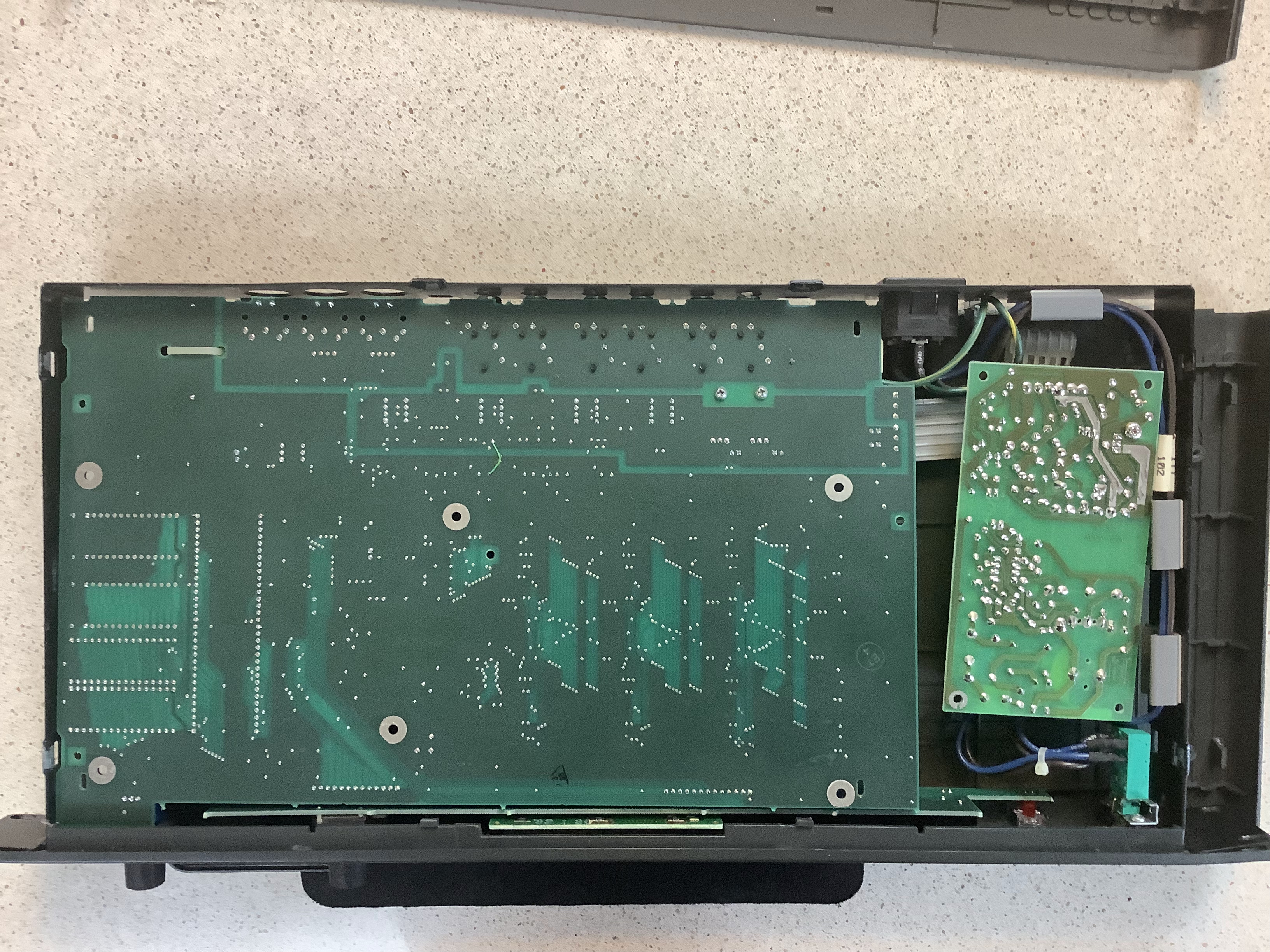
This is the bottom half-case removed.
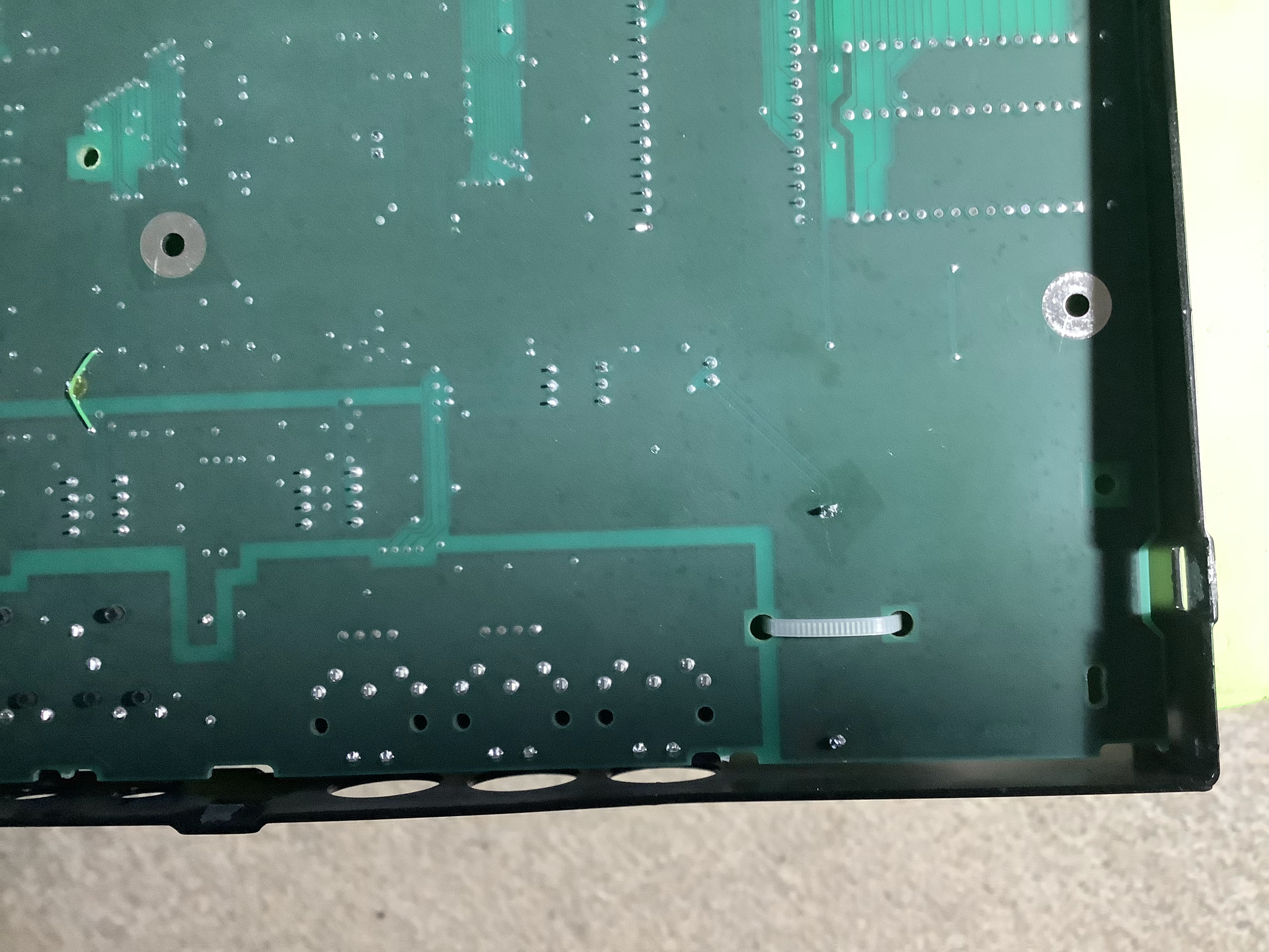
Note the bridge wire in the middle of the board about 2" below the top (rear face) of the picture. Use care when handling. Its difficult to see but the positive side of the battery is the bottom connector below the tie-wrap has two board conductor s going downwards to the right at 45°. There are no board conductors to the top solder connection on either side of the board. So the negative conductor connects to the ground plate inside the board where the board is opaque.
:
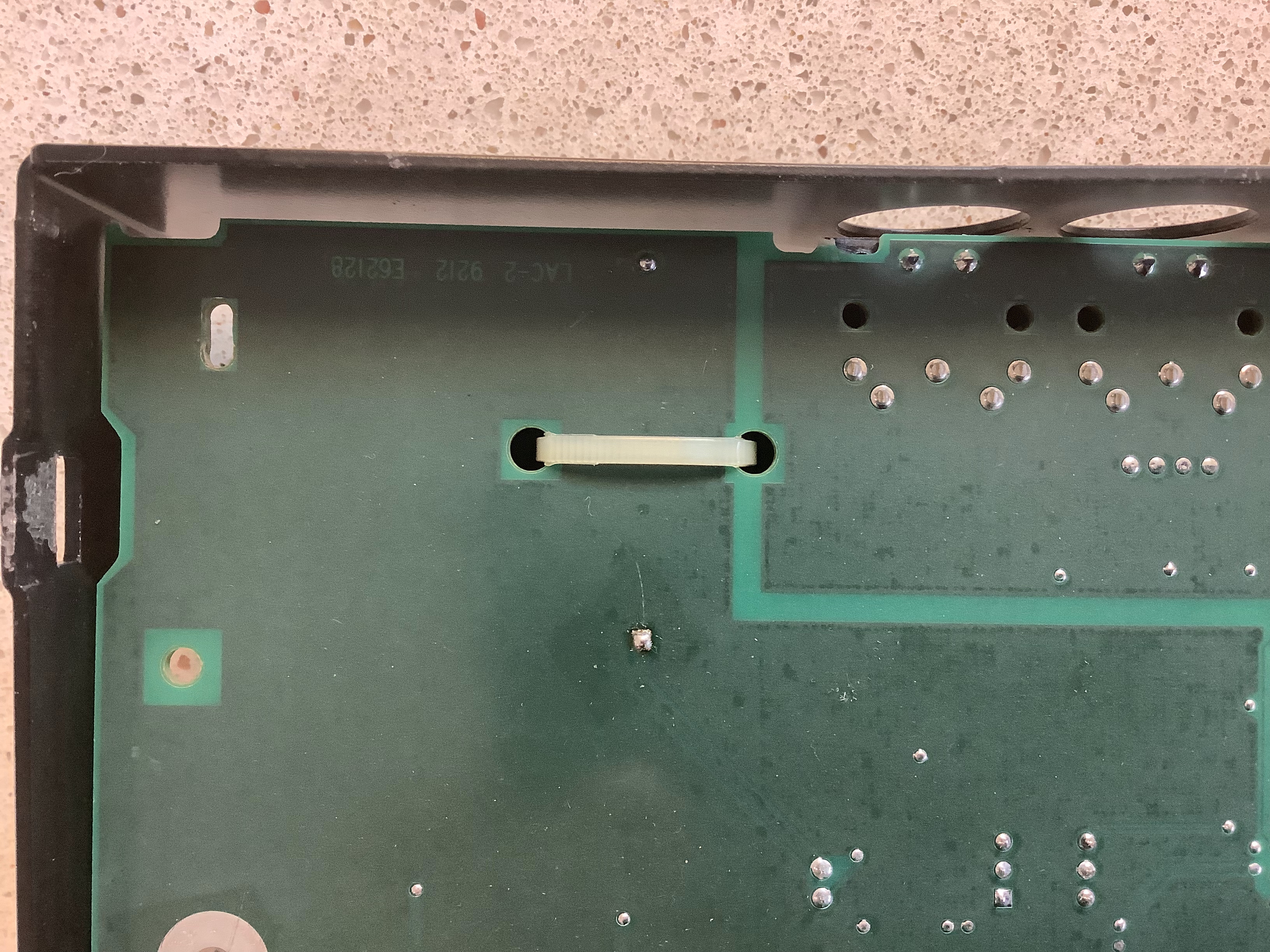
This pic shows a close up of the new battery's solder on the bottom of the old board. All these pics can be be viewed full size if you click on them.
Square soldering. Machines did this.
:
New Solder Bottom of Board
I had a matching color of tie-wrap and used it. You can see how messy my soldering work is. But the board works so its OK.
I used a $30 (12/2021) Weller with a rheostat. With it I used small diameter lead solder, a set of tips including a fine point, a tip cleaning station, and a solder sucker. Pre-heat the iron with a flat tip to 380°-420° F. I removed the old battery's conductors by tugging on the battery while applying heat to the bottom of the board. I used a 6" section of US railroad rail as a support but whatever works for you. If you are not careful you will break it. The holes filled up. I tried to heat the solder and use the sucker. I had no luck so I used standard solder wick on both sides of the board. Got the external solder off but the holes were still full. I let the iron cool and switched out the tip with the pointed tip and reheated the iron. The holes in the board are square. You can penetrate the board with the tip but don't do it for too long, at too hot a temperature, or change the size of the fiberglass board opening. I inserted the hot tip on one side while applying wick to the other. I had to flip the iron and wick and do it from the other side to clear the hole. When the opening looked big enough I dry tested penetration. Tin the tips of the battery. It's a lithium battery it could blow up and burn your face and fingers off. Not to hot and only for short periods do you apply heat to them. Tin then solder, only two short heat applications, and it's done. But first tie-wrap the battery to support it during the operation and leave it when you are finished. Test it before the case is put back on. Set it on an insulative surface. I use a neoprene pad. Don't touch it inside or you could die. If you're uncomfortable with this hire a professional. Plug it in and turn it on. I tested it using it's diagnostic function allowing it to reset all the RAM voices which weren't working anyway. The RAM tested good. I changed the name of the first RAM instrument and saved it. Turned it off then on again and the changes stuck so it worked. It looks like a cold solder but it isn't.
:
New Battery In Place
I signed off on my work and closed the case up.

:
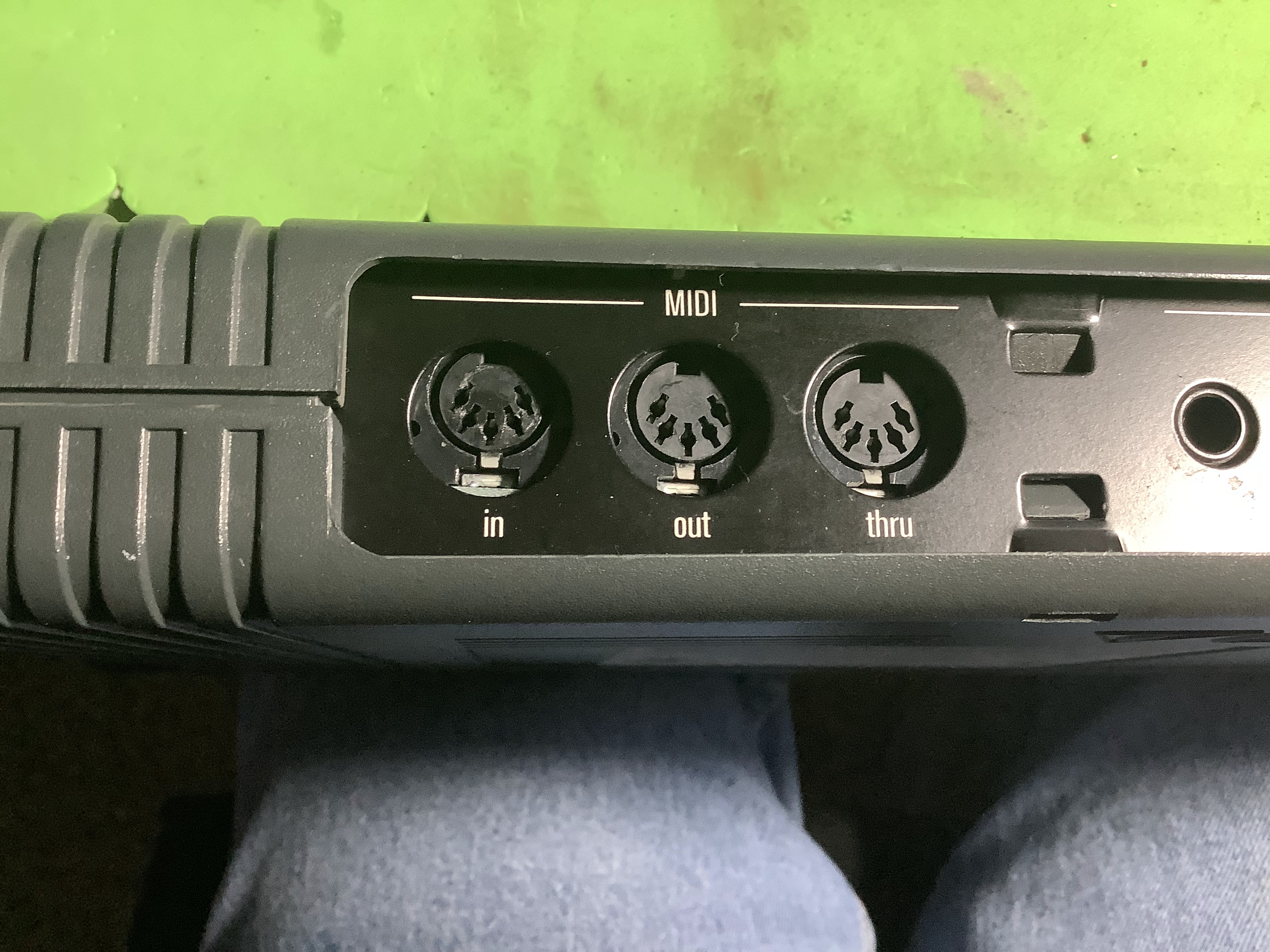
The back face did not align with the MIDI In. I could use the connector so I did not correct the issue by reopening the case again. There are a few tiny plastic parts on the case bottom that support the board. Two broke, one befor I opened it and one when I was working on it.
:
Next I'll need to reload the factory voices (64 through 127) from a factory sysex file. I'll use Cubase for that.
:
:
: