EARLY DESIGN RHODES PIANOS - MAINTENANCE AND REJUVENATION
This Chapter of the manual will be devoted to maintenance procedure and to description of the ways in which the various vintage models can be adapted to newer standards.
- Suppose you have a Piano of the vintage depicted in Figure 8-1 and wish to bring it up to current sound standards. Proceed as follows:
- Examine the condition of the Hammer Heads. If the grooves are not more than 3/16"
(4.762mm) deep, they can be reshaped by sanding off the outer surface. To
accomplish this, construct a shaping tool from a 6" (152.4mm) length of wood to
which has been cemented a piece of very rough sand paper. Beginning at Points A
and Al work upward toward the crown - taking off enough of the outer layer of felt to
remove all trace of the groove (Figure 9-1).
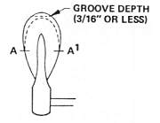
Figure 9-1. Tear Drop Hammer Head - Groove Removal
It should be noted that by the method chosen in this shaping process, you have a measure of control over the "striking line" (the point of Hammer contact along the length of the Tine).
Suppose Point A (Figure 9-2) is the optimum point for best tone and volume response. You can shape the Hammer so that the peak of the felt is left or right of center in order to accommodate to Point A.
You can determine the exact location of Point A by removing all the Mounting Screws from the Harp so that it can be slid back or forward on the Support Blocks. With the Harp free to move, slide it back or forward as you strike the Key until you locate the point of maximum power response. Next, mark this point on the Tine with a felt pen, slide the Harp to original position, with Hammer raised, mark a spot on the Hammer Tip where the Felt Tip should be shaped. This procedure should be repeated about every 6th Hammer throughout the scale. The intervening Hammers can be shaped to the "curve" thus developed.
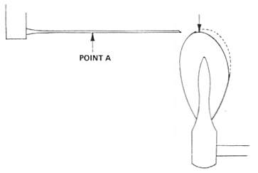
Figure 9-2. Tear-Drop Hammer Head - Reshaping to Striking Line
- Next, test Felt hardness by playing the Piano through the mid-range. If the tone quality is harsh, indicating excessive hardness of Hammers, the Felts can be softened by the "Voicing" process. This is accomplished through the use of a Voicing tool, available in any piano supply house. Failing this, embed a common sewing needle in a hand drill, then "drill" the needle directly into the Felt at several points in the striking area.
- If the Hammer Heads are too badly worn for salvage, remove all Hammer Assemblies and install Replacement Hammer Assemblies. The Hammer Assembly will come complete with Flange and Bridle Strap mounted. It will appear as shown in Figure 8-4A, without Tip.
Proceed as follows:
- Remove all Damper Shoes by sliding forward (Figure 7-1).
- Unscrew Flange Screw and remove Hammer by sliding Bridle Strap out over Damper Arm.
- Mount the new Hammer Assembly by sliding the new Bridle Strap over the Damper Arm then by securing the Assembly with the Flange Screw.
- Slide all Damper Shoes back into place.
- Create a 1/8" x 3/8" x 3/8" (3.175mm x 9.525mm x 9.525mm) shim and glue into place on the Hammer Head as shown in Figure 9-3. This is necessary in order to bring the Hammer Tip up to the full height of the one replaced.
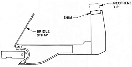
Figure 9-3. RHODES Hammer - Shim Placement
- Secure all Neoprene Tips following the instructions given in the Kit.
- The new Bridle Straps are slightly shorter than the old, resulting in a lower rest position of the Damper Felts. Adjust these upward to suit by bending the Malleable Wire Damper Arm (Figure 9-4).
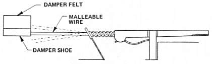
Figure 9-4. Early Design Damper
- Carefully peel off the red woven Felt from the cam curve of the old Hammers, exercising care to leave a smooth, clean surface, and cement to the top of the Key Pedestal. This applies whether the Key is as shown in Figure 8-1 or Figure 8-2.
- Suppose you have a Piano of the vintage depicted in Figure 8-4 but with the type Tone Bars as shown in Figure 7-2, and you wish to restore it. Proceed as follows:
- Remove all Felt Hammer Tips with a jack knife. Make certain that the maple Hammer Head surface is clean of all Felt and old glue. If the Hammer Head is of the variety shown in inset Figure 8-4B, remove the back shoulder with a pair of end cutters in order to provide ample surface for the Replacement Neoprene Tips (Figure 9-5).
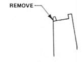
Figure 9-5. Double-Shoulder Hammer Head
- Using 3M Super Weatherstrip Adhesive No.8001 available at auto supply stores, or a similar bonding agent, cement the Neoprene Tips following instructions given in the Hammer Tip Replacement Kit.
- Remove all Tone Generator Assemblies by removing all Tone Generator Mounting Screws (Figure 8-1).
- Mount all new Tone Generator Assemblies following instructions given in the Tone Generator Assembly Replacement Kit.
- Adjust Timbre. See Timbre Adjustment, Page 4-6.
- Adjust Volume. See Volume Adjustment, Page 4-6.
- The Felt Tips are slightly taller than the Neoprene Tips, so escapement must be re-established. See Page 4-1.
- Remove the Harp Mounting Screws (including the Hinge Screw) on the left (Bass) side of the Harp (Figure 9-6, 9).
- Refer to Step 3., Page 4-6.
- When you have located this new Harp position to your satisfaction, sink two new holes in the maple Side Support Blocks (use a No.10 drill), then secure the Harp by remounting the Screws. Next, remount the Hinge by drilling a new hole (No.10) in the side of the Harp Frame. Exercise extreme care in guiding your drill through the steel so as to avoid plunging the drill into the Pickup. If the Harp/Action Assembly is out of the Cabinet, a new hole can be drilled in the side of the Harp Support Block to relocate the Hinge, thus avoiding the possibility of damaging the Pickup.
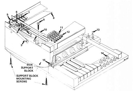
1. Tines
2. Dampers
3. Harp Hinge
4. Pickups
5. Preamp Jack
|
6. Pickup Arms
7. Pickup Mounting Screws
8. Damper Release Bar
9. Harp Mounting Screws
10. Typical Tone Bar
|
11 & 12. Tone Bar Adjustment Screws
13. Balance Rail Guide Pins
14. Front Rail Guide Pins
15. Nameboard Mounting Screws
|
Figure 9-6. RHODES Early Design Harp/Acfion Assembly - Cut-Away View
TOC - 1 - 2 - 3 - 4 - 5 - 6 - 7 - 8 - 9 - 10 - 11